What is a dc-dc inverter used for?
Konwerter napięcia zapewnia stabilne dostarczanie energii elektrycznej. To ważne dla wydajności i trwałości sprzętu elektronicznego. Przetwornice DC/DC są cenione za swoją efektywność energetyczną.
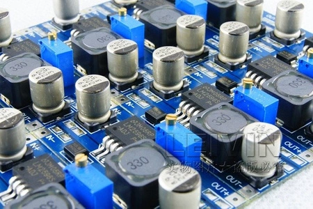
DC/DC converter is an important device in the world of electronics. Its main task is to change the DC voltage from one level to another. It is crucial for efficiently powering devices, from smartphones to advanced industrial systems.
DC/DC converter is an important device in the world of electronics. Its main task is to change the DC voltage from one level to another. It is crucial for efficiently powering devices, from smartphones to advanced industrial systems.