Add products by adding codes
Add a CSV file
Enter the product codes that you want to add to the cart in bulk (after a comma, with a space or from a new line).
Repeating the code many times will add this item as many times as it appears.
FOX from Multiplex - the first RC model
2015-11-12

FOX RC motor glider - FOX from Multiplex - the first RC model
Link to model: RC models Fox dart glider
Here I wanted to provide a detailed account of the construction and flying of the FOX model with conversion to a RC powered and controlled model.
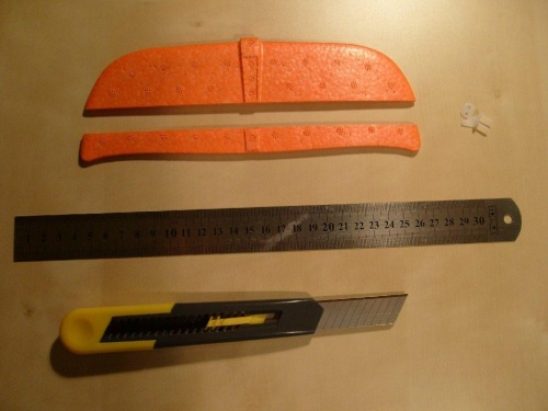
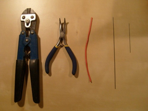
I will start with the tools that I will need in the near future.
Probably the most important thing here is a very sharp knife (kitchen or pocket knife is out), it is worth investing in good knives (I recommend OLFA company).
However, the best tool is a surgical scalpel.
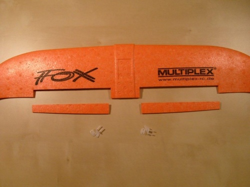
I start my work by cutting out the ailerons in the rudder and wings.
I cut the rudder of the height all the way to the width (at the fuselage) of 16 mm
The ailerons in the wings are 18 mm wide and 130 mm long
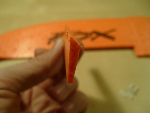
Then, in the cut ailerons, I cut off the edge that connects to the stabilizer along its entire length so as to get a sharp even edge. The idea is that the aileron hinge will be made on this edge. The sharp edge is to be from the top of the wing or stabilizer.

The ailerons for the rudder and wing I glued, on glue, UHU POR. I greased the adjacent corners of the aileron and rudder with a thin layer of glue, waited 5min and joined them together. It is a fairly easy method, and contrary to appearances, it is strong, and too strong.
To begin with, I do not recommend this method, because with more glue the aileron works very hard. I recommend doing it with duct tape, as I did on the first model (FOX glider). It is a good idea to pre-lubricate the area with UHU POR adhesive and wait 30min before applying the tape.
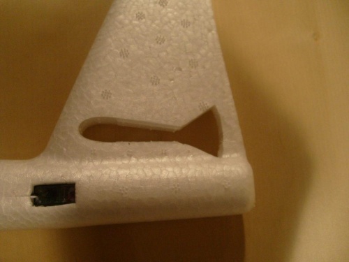
In order for the rudder aileron to work freely, a piece of the vertical stabilizer must be cut into the fuselage.
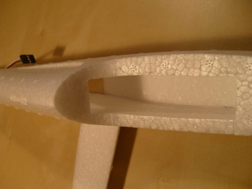
Another important thing to do is to prepare the space in the model's hull.
Since this is to be a front-drive model, it will weigh down my engine and I need to give a larger battery, and this will cause problems with an overly heavy bow (it will not be possible to balance the model well)
Therefore, I cut the fuselage differently as before. The way I did it was to cut the bottom of the fuselage about 10 mm thick from the bow to about 20 mm behind the wing.
There is then access to the entire length of the model and you can cut out the space for the equipment very nicely.
After making the cutout, I re-pasted the front part of the underside of the fuselage. In this part I have access from the top through the cabin.
After a preliminary check, it turned out that the battery probably needs to be mounted under the wing near the center of gravity, so I will make a removable underside for this part. On the other hand, it is likely that the cabin will be glued permanently.

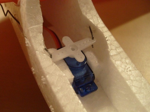
No-name rudder servo 4.5g
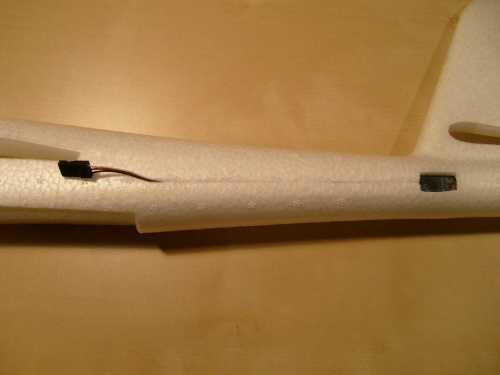
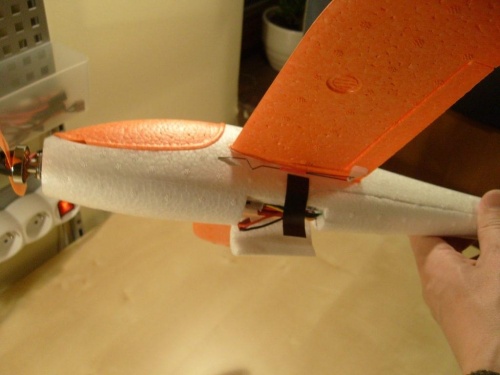
I decided to give the servo at the back of the model (to add weight to the rear)
So, it is necessary to cut out the place for the servo (after careful fitting, so as not to weaken the fuselage too much).
The servo is only pressed in, there is no need to fix it otherwise.
Insert the cable from the servo into the notch made in the fuselage (with a knife to a depth of 4 mm)

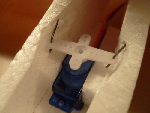
We make aileron pushers
Now it will show how to make easy aileron pushers
You will need thin steel wire (preferably 0.8 mm), I used 0.6 mm for the rudder height for the ailerons 0.8 mm, and a fairly hard insulation from a cable with a hole inside the. approximately 1 mm.
Everything shown in the pictures. Pusher made this way can be used on small models and is easy to put on and take off. After installation, give drops of cyanoacrylate into the tee (be careful not to flood the servo or aileron levers)
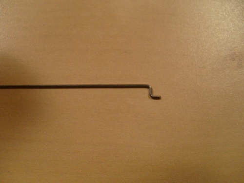
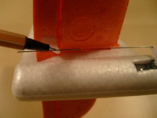
Here, after fixing one side of the pushrod in the servo and aligning the servo and aileron equally at zero, we mark the place where the wire is bent.
Next, we put a section of 20 mm shirt from the cable on the wire and bend the other side of the pusher, and cut off the unnecessary piece of wire.

Next, a second piece of wire (about 50 mm) is inserted into the tee, which is a pin for the pusher when inserted into the aileron lever.

We are installing the ENGINE and the regulator
outrunner F2418 2350KV weight 17g REGULATOR 10A
Since it does not have a removable handle, I had to screw it on differently.
I used quite long screws (some leftover toy) Mm,5 long 30m.
I cut off the heads and after making holes in the bow of the model, I pasted them on CA cyanopane glue.
Just be careful when doing this that the glue does not seal the entire thread, it is best to lubricate the protruding thread with grease.
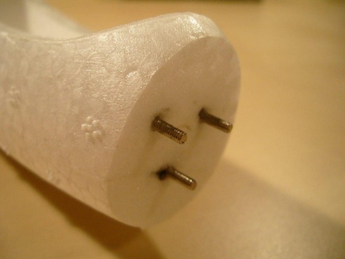
Now all you have to do is screw in the nuts that fix the position and alignment of the motor and bolt the motor on (this was the hardest thing to do)

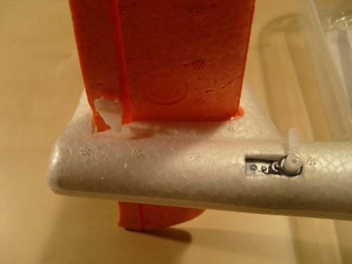
Now using the same method as for the elevator rudder, I am making aileron pushers for the wing
Earlier I fixed the place for the aileron servo. I gave them in front of the wing so that the movement of the pushrods is as perpendicular as possible to the aileron hinge.
The grommets in the fuselage for the pushrods can be made with a piece of wire heated with a lighter, just be careful and test on some piece how it melts (so as not to make too big a hole)

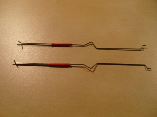
There is an additional "V" shaped bend made at these pushrods, it allows to adjust the length of the pushrod by dogging and bending this bend.
With the ailerons of the wing I had to use such an option, because they are made on a single servo and there is no possibility to set the zero (with the help of the transmitter) for both ailerons separately.
Here a small overview video of how the ailerons work in a FOX model
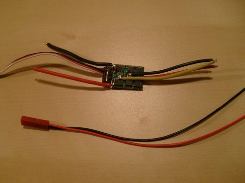
I removed the cover from the regulator and decided to solder the motor wires directly to the regulator (I advise those less familiar with a soldering iron against such a connection).
The reason I did it this way is to save weight (I wanted the front as light as possible) and the cables from the engine are then routed more nicely.
The wires from the regulator to the battery were also replaced with ready-made ones with connectors.
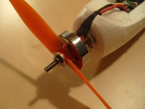
Propeller and propeller mounts
Propeller mount (the engine had a threaded axle)
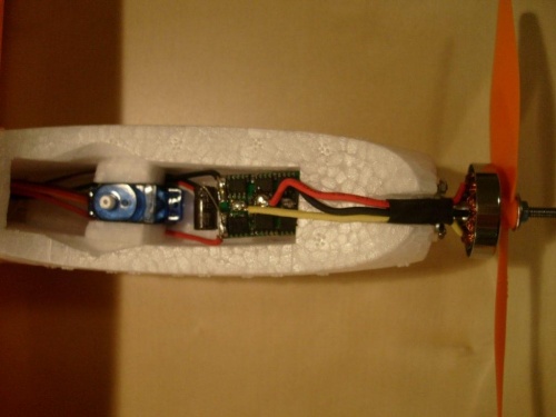
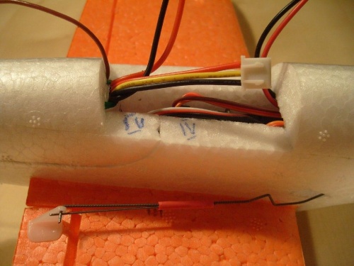
Now having installed most of the components in place (only the receiver is missing, but it will go under S.C.) I can determine the exact location for the battery.
By moving the battery front back, I found a place where the center of gravity was 51 mm from the wing's leading edge.
Over the length of the entire battery, I decided to permanently glue the underside. This will strengthen that part of the fuselage, weakened by the battery cutout.
After extending the cable to the altitude servo and inserting it inside the fuselage, I placed the receiver in the fuselage under the wing and connected everything.
I checked all the equipment to make sure it works properly, that the servo levers have zero settings in the right place, and that the receiver and regulator with the motor work properly.
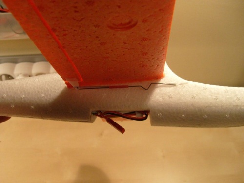
A positive test was followed by final assembly:
- gluing the wings and stabilizer to the fuselage (I ran over the folding of the fuselage with the wing and rudder with UHU POR glue)
- immobilize the aileron servo by sealing with UHU POR glue (do not use thin CA)
- screwing the lever to the servos
- i cut channels for ventilation of the front chamber of the glider (in the cabin)
- i glued from EPP additional baffles inside the fuselage (for reinforcement)
- i made a hinge out of duct tape for the opening fuselage cover, and a washout out of duct tape
- i fitted a small rubber cap from GWS to the propeller
And this is how it looks in its entirety
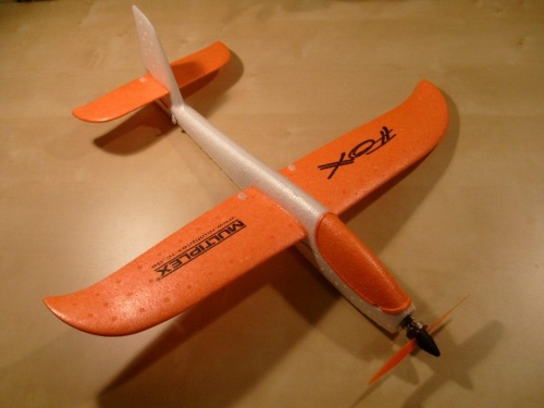


The weight of the ready-to-fly model is 133g.
Testing the engine, this thrust is sufficient for vertical flight on 3/4 gas.
According to the manufacturer, the motor thrust on a 5 × 3 propeller is 165g at 5A.
Now it's left to charge the pack, and the model can be tested.
Notes on the volatile properties of the model.
- engine power sufficient for vertical flight
- calm flight on 1/3 to ½ throttle (like ES)
- the model is as self-standing as ES
- doesn't like large rudder deflections (that's why it's necessary to correct rudder deflections)
- loses lift and is lost to the wing. After limiting leaning, I was unable to get it into such a state
- flies very well as a glider
- wide range of speed (can fly fast - powerful engine and glide)
- barrels come out in a clumsy way (this is not an acrobat - lack of symmetry and design)
- loops are very nice and clean
To sum up, a very nice model to fly, small, cheap (I will present the equipment and the cost of construction), very easy to control (like Easy Star), and very resistant (mine had several hard encounters with the ground-no damage) and a flight time of 20-30mins.
The only drawback of the model is that it is small, it is impossible to fly high and far (just why)
The only thing I have noticed is flying calmly, the model mouse from side to side, as if my rudder (which I do not have a rudder) vibrates.
But I suppose it may be the fault of the rather long antenna sticking out of the back of the model.
Here a video of the flight
NOTES to the model
In models without elevation (or tip-ears), to make a turn on the ailerons, just swing the ailerons for a moment, the model tilts and you can make a turn with the altitude rudder. And in this model this is not the case, the ailerons must be swung all the time, except that, in order to model airplane lean, you need to lean harder, so that you can then reduce the lean a bit. It's not that easy, for someone starting to fly. I only realized this yesterday when in a turn I had to take my right hand off the apparatus (model 1).
I believe that for someone starting out in modeling, the ailerons should be abandoned on this model in favor of a directional rudder. The model will then be very similar to the ES (well, except maybe for the landing speed)
Directional rudder control will work out well for the model.
Show more entries from
November 2015