Add products by adding codes
Development mobile platform - microcontroller support and bluetooth control

In this section (I part) will continue to deal with the mobile platform, but this time it will be a slightly more developed version, in which I will use the Arduino UNO, and the control will be implemented via bluetooth communication.
Thanks to wireless communication, it will be possible to control the platform from virtually any device equipped with a bluetooth module such as a smartphone or tablet.
In addition, operation will be easy with dedicated phone apps.
So let's start with assumptions, to begin with the vehicle must be as simple as possible, then you will program and connect additional components.
The first step is to connect the H-bridge to the Arduino. The L298N bridge is already well known to you from previous posts, plus it is cheap and readily available.
The connection is as follows: The pins responsible for the speed of each channel are jumpered to +5 V, so they will rotate at max. speed, and we will only change the directions of rotation by applying high states to the appropriate pins from IN1 to IN4.
We will immediately reserve pins to control the speed of each channel, so that during development we will not run out of pins in the Arduino. Since the Arduino has a selection of 6 pins with which we can adjust the PWM signal, we will choose such pins that are next to each other. So the hook-up is as follows:
- Pins responsible for the direction of rotation:
L298N - Arduino
IN1 - 4
IN2 - 7
IN3 - 8
IN4 - 9
- Speed control pins:
ENA - 5
ENB - 6
The bridge we have connected, now you can already be tempted to control, so let's connect the Bluetooth module. In my case, it is the HC-06, which can only operate as a SLAVE. BT communicates with the Arduino via the UART port, so I connected it to pins 2,3. Why not under pins 0 - RX and 1 - TX? Because there is a system uart port, and we need an additional one (so that we can upload new programs with the connected module), and for this purpose the Software Serial library will help us, but about this a little later, when discussing the program.
I have mentioned BT modules in previous posts dedicated to them, as well as in the creation of a weather station. So, if you are interested in the topic and want to expand your knowledge in this area, I refer you to the series on Bluetooth modules HERE, as well as a weather station HERE.
Connecting the BT module is not easy, because the interface operates at 3.3V, and the Arduino, as we know, at 5V. By connecting directly, we can damage the BT module, so we need a level converter, or just a simple resistive voltage divider on the RX line of the BT module. Why only on the RX line? Because this is the line receiving data by the BT module, and the TX line is the line sending data to the Arduino. However, the module's power supply is 5V, so the connection looks like this:

That's all as far as the mechanical parts and electrical connections of the vehicle are concerned, now we move on to the application we will control the robot with. Download from the Google PLAY store bluetooth electronics here is the link to the site keuwl and this original design.
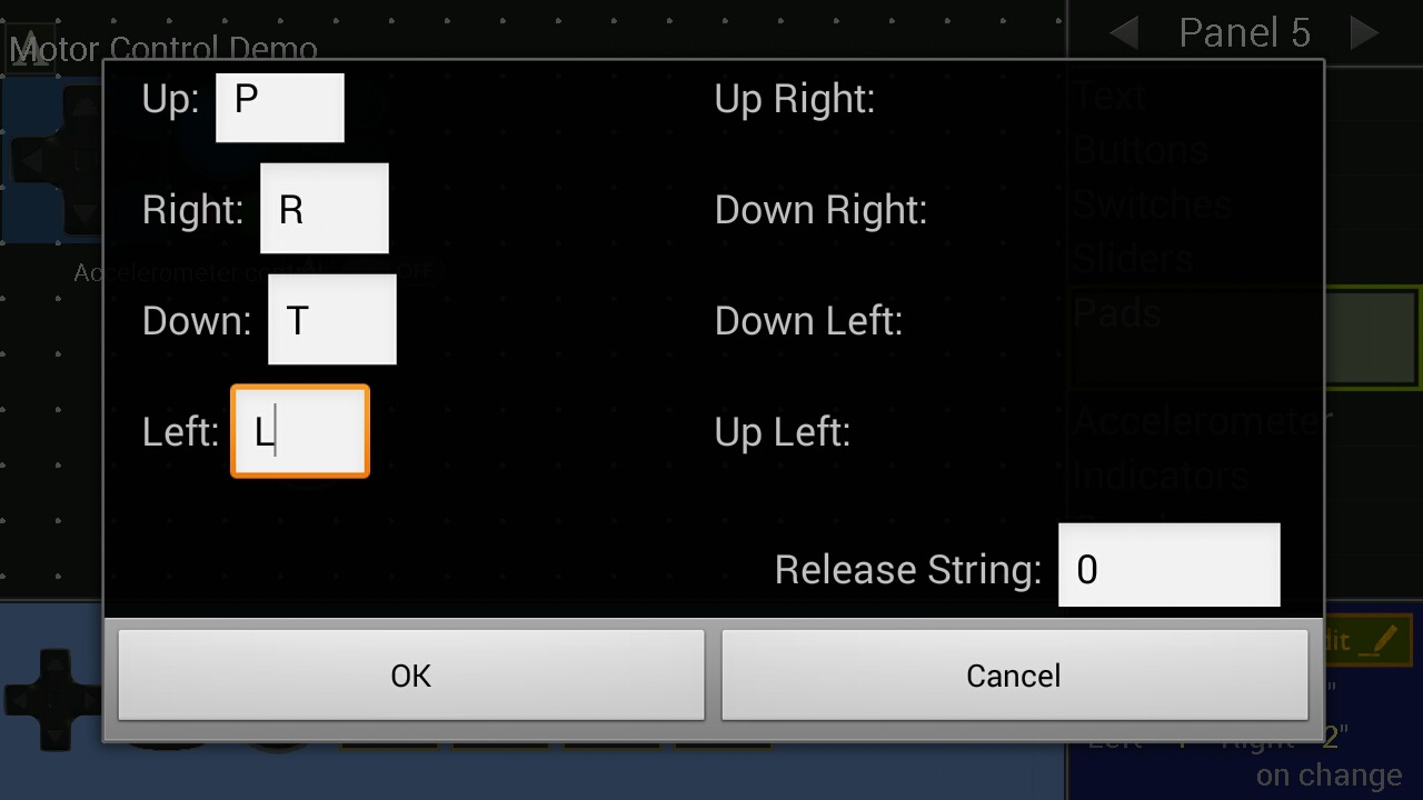
The application works in a very simple way (see the detailed description of the article on BT communication and weather station links above), through UART communication, it sends, for example, uppercase or lowercase letters depending on whether you press the switch or not. In addition, you can set whether the sign sent is only once during the change, or all the time the button is pressed. This allows us to quote specific "tasks" to them after the Arduino receives the appropriate characters. The same principle is with communication in the reverse direction.
Then we can move on to the program uploaded to the Arduino robot, and later we will deal with the control, or smartphone app. Below is a sketch, in which I tried to describe each activity in detail, also invite you to get acquainted:
[CODE]
/*
 *
 Bluetooth controlled mobile platform HC-05 /06 ver. 1.

*/

#include SoftwareSerial mySerial(2, 3); //RX, TX // for BT connections in reverse

char BluetoothData; // constant that receives data from bt

// engines:
int motorPPpin = 4; // forward right engine
int enginePTpin = 7; // to back right engine
int motorPPWM = 5; // PWM motor R
int motorLPWM = 6; // PWM motor L
int engineLPpin = 8; // forward left engine
int engineLTpin = 9; //to the back left engine


void setup() {{|br />
 Serial.begin(9600); // comp-rd transmission

 mySerial.begin(9600); // start ardu-BT transmission

 //motors as outputs
 pinMode(motorPPpin, OUTPUT);
 pinMode(motorPTpin, OUTPUT);
pinMode(motorPPWM, OUTPUT);
 pinMode(motorLPWM, OUTPUT);
 pinMode(motorLPpin, OUTPUT);
 pinMode(motorLTpin, OUTPUT);

 //setting to LOW
 digitalWrite(motorPPpin, LOW);
 digitalWrite(motorPTpin, LOW);
digitalWrite(motorPPWM, HIGH); // set to high state to make the motors rotate well unless you have jumpers connected
digitalWrite(motorLPWM, HIGH); // also pwm in high state
digitalWrite(motorLPpin, LOW);
 digitalWrite(motorLTpin, LOW);


void loop() {{|br />
 if (mySerial.available()) { // if there is data in the buffer then receive

 BluetoothData = mySerial.read(); //receiving data from BT

 if (BluetoothData == 'P') { // if "front" is pressed then forward
 digitalWrite(motorPPpin, HIGH); //right motor, front ON
 digitalWrite(motorLPpin, HIGH); //left front motor ON
 }


 if (BluetoothData == 'T') { //if read backwards "T"
 digitalWrite(motorPTpin, HIGH); // right rear motor ON
 digitalWrite(motorLTpin, HIGH);// left rear motor ON
 }


 if (BluetoothData == 'L') { // if left
 digitalWrite(motorPPpin, HIGH); // this is the right front motor ON
 }

 if (BluetoothData == 'R') { // if right then left front motor ON
 digitalWrite(motorLPpin, HIGH);
 }


 if (BluetoothData == '0') { // if nothing pressed then stand
 digitalWrite(motorLPpin, LOW);
 digitalWrite(motorPPpin, LOW);
 digitalWrite(motorPTpin, LOW);
 digitalWrite(motorLTpin, LOW);
 }


 //delay(10);// wait 10 ms

 while (Serial.available() > 0) {{|br /> mySerial.write(Serial.read());

 }

 while (mySerial.available() > 0) {{|br /> Serial.write(mySerial.read());
 }
 }
[CODE/]
Now having the code, we can upload it to the Arduino board.
Now that the program is behind us we move on to the bluetooth electronics application, in which we run the example "Motor Control Demo"

Then, by pressing the "edit" button, we change the characters transmitted when the buttons are pressed, as well as when they are released.


Coming out of the edition, we connect to the Arduino platform (via the BT module) and check the operation of the program:


Once connected, we open the example and can enjoy the remote controlled mobile platform.
Soon there will be another blog post, in which I will expand the platform with additional "gadgets", "bytes",
such as lights, GPS, MPU, FPV, various types of sensors and others.
Yotube video...


